RLC Circuit Calculator
Analyze series or parallel RLC resonance, impedance, phase, Q factor, and AC current.
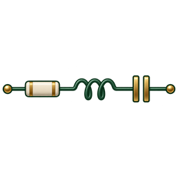
f₀ = 1 / (2π√LC) BW = f₀ / QCalculations stay in your browser. Share links contain the input values you choose to share.
How to use this calculator
- Choose the series circuit or the three-branch parallel circuit.
- Enter the resistor, inductor, capacitor, and evaluation frequency.
- Enter a sinusoidal source voltage in RMS units to calculate current and real power.
- Select “Evaluate at resonance” to inspect cancellation of the reactive components, and compare source current across the frequency sweep.
A quick worked example
For L = 10 mH and C = 1 µF, resonance is 1.5915 kHz. In series with R = 10 Ω, Q is 10 and bandwidth is 159.15 Hz. At resonance, a 1 V RMS source supplies 100 mA and R dissipates 100 mW. A parallel circuit with R = 1 kΩ has the same resonance, Q = 10, and 159.15 Hz bandwidth; at resonance it draws 1 mA from that source.
A few useful answers
What happens at resonance?
For the ideal circuits shown, f0 = 1/(2π√LC). The inductive and capacitive effects cancel at the input, leaving a real impedance equal to R. Series impedance is at a minimum, while parallel impedance is at a maximum.
What does bandwidth mean in each mode?
For series RLC driven by a constant voltage, bandwidth describes the current response’s −3 dB points. For parallel RLC, it describes the impedance response’s −3 dB points, equivalent to a voltage response under constant current drive. With a fixed voltage across the parallel circuit, resistor power stays V²/R; it does not peak at resonance.
Which Q formula is used?
Series: Q = √(L/C)/R. Parallel with three independent R, L and C branches: Q = R√(C/L). Both use bandwidth f0/Q. A lossy inductor with its resistance inside the inductive branch is a different circuit.
What do the phase and component results mean?
Impedance phase is voltage phase relative to source current. Current phase is its negative. The current-versus-frequency chart holds your entered RMS voltage constant and shows source current, with a peak in series mode and a dip in parallel mode. Series component voltages and parallel branch currents are RMS magnitudes; reactive quantities are not added as plain magnitudes.
Model & assumptions: Ideal sinusoidal steady-state model with a fixed RMS voltage directly across the input terminals. The explicit R is the only loss. Inductor winding resistance, capacitor ESR, source impedance, parasitics, tolerances, saturation, initial conditions and transient response are not modeled.
Electronics Tools & Calculator
Also available for iOS, Android, and Windows.