RL Passive Filter Calculator
Design a low-pass or high-pass RL filter and inspect its gain and phase response.
fc = R / (2πL) τ = L / RCalculations stay in your browser. Share links contain the input values you choose to share.
How to use this calculator
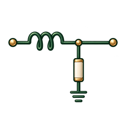
- Choose low-pass or high-pass. The diagram shows which component the output is measured across.
- Calculate cutoff from R and L, or solve for one component at a target cutoff.
- Enter an evaluation frequency to inspect gain and phase.
- Review the response plots and choose actual components with suitable operating limits.
A quick worked example
With R = 100 Ω and L = 10 mH, cutoff is 1.5915 kHz and the time constant is 100 µs. At 1 kHz, low-pass gain is −1.445 dB and phase is −32.14°. At cutoff, both modes have magnitude 0.7071 (−3.0103 dB); phase is −45° for low-pass and +45° for high-pass.
A few useful answers
Which component is the output measured across?
The low-pass circuit uses a series inductor and shunt resistor, with output across R. The high-pass circuit uses a series resistor and shunt inductor, with output across L. The cutoff frequency is R/(2πL) in both ideal circuits.
How does changing R or L move cutoff?
Increasing resistance raises the cutoff frequency. Increasing inductance lowers it. The time constant is L/R, so it changes in the opposite direction to cutoff.
Does this include the inductor’s winding resistance?
No. Real inductors have winding resistance, core loss, parasitic capacitance, saturation and self-resonance. Those effects change the response, especially near the device’s operating limits. This tool uses an ideal inductor.
Can I attach a low-impedance load?
The modeled output is unloaded, meaning effectively infinite load impedance. A connected load changes the transfer function. Include source and load impedances in a full circuit analysis when they are significant.
Model & assumptions: Ideal first-order RL network, zero source impedance, infinite load impedance, and positive component values. Winding resistance, core loss, parasitic capacitance, saturation, self-resonance and component tolerances are not modeled.
Reference: Analog Devices — Low Pass and High Pass Filters ↗
Electronics Tools & Calculator
Also available for iOS, Android, and Windows.